
Asphalt spray truck is mainly composed of chassis, thermal insulation tank, asphalt pump, heating device, spraying system, operating system, etc. It is a special operation vehicle for spraying asphalt. Due to the relatively complicated structure of the asphalt spreader, it requires professional operators to carry out construction operations. Many new operators lack a certain understanding of the structure of the truck. Here we will share the structure of the asphalt spreader with you.
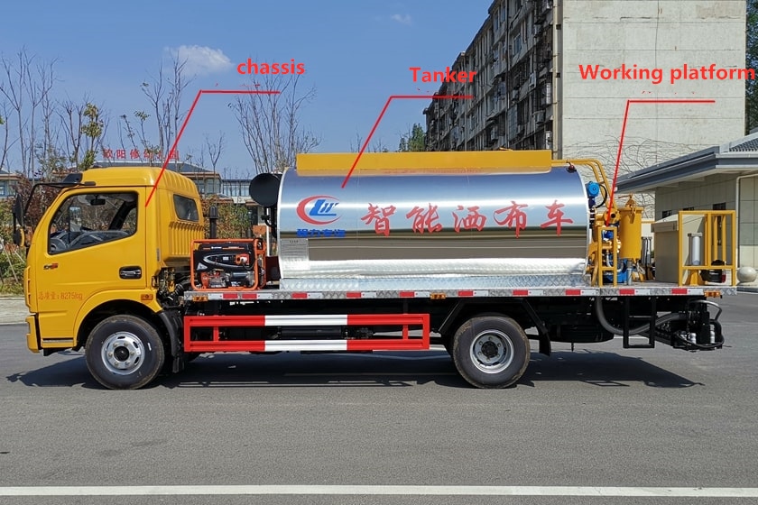
As shown in the figure above, this car is a schematic side view of a 6 cubic asphalt spreader, using Dongfeng Dolka chassis (to provide power for the car to run and the asphalt pump), three-layer insulation tank (for loading asphalt), asphalt pump, The heat conduction oil pump, operation platform and related valves and switches are installed on the rear working platform. Below we will show you a partial function diagram of the car.
1. Schematic diagram of tank mouth of asphalt spray truck
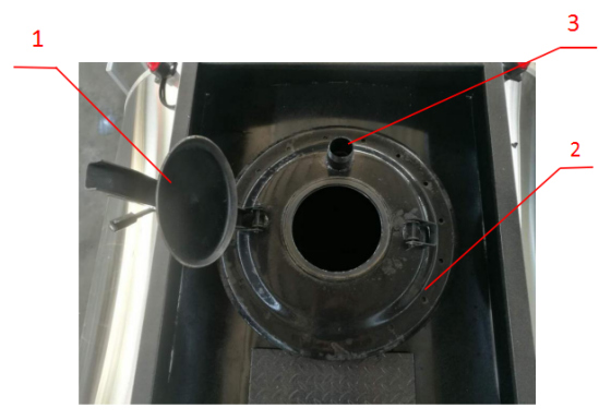
Operation method of filling asphalt: drive the asphalt spray truck under the filling pipe, first put all the valves in the closed position, open the small cap of the fuel port on the top of the tank, put the fuel pipe in, and start filling asphalt, after filling, Close the small filler cap.
2. Structure diagram of heating device for asphalt sprayer
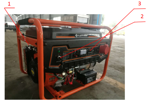
Operation method of heating operation: turn on the main vehicle power supply, start the gas oil generator, open the generator damper → open the start lock → close the damper → let the voltage stabilize, turn on the relay switch, and the heat conduction oil pump in the back will turn up. When the set temperature is set to the desired temperature, the burner is turned on, and then the burner will work in 20 seconds. After heating up to the required temperature, turn off the burner, let the heat transfer oil pump circulate for 5-10 minutes, let the heat transfer oil temperature balance, and then turn off the gasoline generator, you can spray operation.
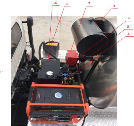
3. Structure drawing of spraying operation device
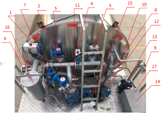

Operation method of spraying operation: remove the rear spray hook, turn on the lift switch next to the electric box, and then open the left and right spray pipes respectively, so that the nozzle is about 260 mm away from the ground, and the height can be adjusted with a chain. Start the engine of the main car, let the air pressure reach above 0.6MP, step on the clutch, turn on the power take-off to start the hydraulic system. Open the oil outlet valve and adjust the width and amount of spray you require. Move the operating state to the ready position, at this time, the asphalt goes from the tank → the oil outlet valve → the filter → the asphalt pump → the left spray pipe → the middle spray pipe → the right spray pipe → the large circulation valve → return to the tank for circulation, circulation About 10 minutes, until the temperature of the nozzle and nozzle is high. According to the recommended gear on the computer screen, the automobile transmission is hung to the same gear, and the sprayer is driven to the specified operating point, and the operating state is switched to the spray position to start spraying. Maintain a straight line and drive to the end, move the running state to the stop position, and the spraying operation is completed.
The above is the structure diagram of the intelligent asphalt spreader. Due to the limited space, it can only be introduced here. For more configuration and related information about this car, please click:
https://www.wltrucks.com/product-category/asphalt-spreader-truck/